Description
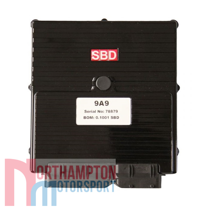
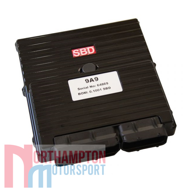
The MBE9A9 is the most advanced ECU that MBE has released to the motorsport market. The technology put into the ECU has been developed through its many years of production car ECU development. This has allowed MBE to produce a very high level ECU but at an affordable price. MBE & SBD have spent the last 3 years refining the software & user interface ready for high level motorsport use.
The MBE9A9 has high side & low side drivers. This means you have the option to either drive the outputs directly from the ECU with no relays or use a low side driver to drive it via relay. The MBE9A9 ECU’s are built to customer specification, we will need your full engine specification with your order.
Full specification can be found below:
Inputs:
Crank Sensor & Trigger Wheel Input
Crank sensors are most commonly of the inductive type, you can normally use the original crank sensor. If your engine uses the hall effect type, MBE ECUs can be built to order. MBE write special code to allow the use of a range of different trigger wheels. Most commonly 60-2(GM/VW/Bosch), 36-1(Ford), 24-1(Suzuki Hayabusa) & 24-2 (Suzuki Busa 2008 & other late Japanese bike engines). Other trigger wheels may become available, download Easimap 6 to check current types. We can supply a range of specialist sensors & suitable trigger wheels for applications that currently have no trigger wheel.
A special piece of software has been written by MBE called soft start. This was produced due to known problem with the standard starter motors, that if the battery got a bit low sometimes the engine would kick back on starting and engage the starter clutch. This would, if you were lucky only damage the starter clutch itself, but if unlucky could break off part of the engine cases. Without going into too much detail, the ECU allows the engine to get up to speed during cranking before attempting to start the engine. If the engine does not reach sufficient speed it will not allow the engine to start, so damage can not occur.
Throttle Position Sensor Input
When used with cable operated throttle:
Throttle position sensors are used to inform the ECU of how much load is being applied. The throttle position sensor informs the ECU rate of throttle change to calculate acceleration fuel & when the throttle is closed, this information can be used to enable the ECU to do idle control.
They are commonly used on single or multi-throttle body applications. They are also used on turbo engines in some applications. Most OE engines have throttle position sensors* as standard, you will be able to configure the MBE to suit.
*Some engines have throttle switches, they look identical to throttle position sensors. Please check to ensure which type you have.
Ignition & Coil Input
The MBE9A9 has eight ignition drives, that can be fired either sequentially or in wasted spark mode, depending on requirements & set-up. The normal MBE9A9 has built in amplifiers so there is no need for expensive external units. (MBE9A9s can be specially built to run coils with built in amplifiers). You can either use coil on plug or wasted coil packs, we have a standard range of coils that we can recommend. If you have a specific coil unit that you wish to use, not in our normal range, you can send it to us for testing with the MBE when ordering a system.
Air Temperature Input
The standard input circuitry allows the use of MBE/Bosch/Nippon Denso/Lucas air temperature sensors, which all normally use the same calibration. You can also create your own calibrations if you require, different circuitry options can be custom built for additional cost.
Water Temperature Input
The MBE water temperature input circuitry allows the use of 2 different types of sensor, either the MBE/Bosch/Nippon Denso/Lucas water temperature sensors (all use the same calibration) (WTS1) or Ford type which uses a completely different resistor value. This is selectable within the ECU. These 2 types are pre-calibrated in the SBD maps, you can also create your own calibrations if you require.
Boost/MAP Pressure Input
The boost/MAP pressure sensor compensates for changes in manifold pressure, most commonly used with turbo applications. The sensor input is 0 – 5V, it is fully calibratable by the end user. The ECU will normally come with calibration either for the MBE/GM sensor (car engine) or a specific engine calibration to suit its standard sensors. The ECU can make changes to fuelling & ignition according to pressure.
Barometric Pressure Input
The barometric pressure sensor compensates for atmospheric pressure changes due weather conditions & altitude. The sensor input is 0 – 5V, it is fully calibratable by the end user. The ECU will normally come with calibration for the MBE/GM sensor (car engine) or a specific engine calibration to suit its standard sensors.
Lambda Sensor Inputs
The MBE9A9 & MBE9A6 ECUs have twin wide band lambda control inputs, which uses the latest specification Bosch lambda sensors. This allows the user to use closed loop fuel mapping via a target lambda map, which can be set at different lambda values for speed & load. If the car is required to pass SVA or MOT tests, the map can be configured by the user to Lambda 1 values to suit the desired requirements. Please note to obtain SVA or MOT test passes you will need use a catalytic convertor. We would recommend the use of a high-flow motorsport cat or cats in order to not compromise the performance of your engine.
Outputs:
Fueling & Injector Output
The MBE9A9 has eight sequential fuel drives, which can run up to 8 injectors between 12 – 14 ohms. These can be set-up for a 4 cylinder engine with upper & lower injectors, 6 cylinder engine or 8 cylinder engine. Other options may become available. The injectors can also be configured in semi-sequential or grouped set-up. The ECU has a 16 bit fuel map, which allows ultra fine millisecond control. This means you can use very high flow injectors & still obtain very accurate mixture control particularly when setting up for SVA & MOT purposes, which can quite often be a problem with less accurate systems.
Shift light & Combined warning systems Output
The MBE9A9 ECUs have warning systems which can be set up to trigger a light or bleeper:
- Shift light: The shift light output is configurable in several ways, it could be set-up as a simple shift light which is purely rpm dependant. If you have a sequential gearbox & supply the MBE9A9 with gear position, you can have a gear dependant shift light.
- Water temperature: The water temperature which will pulse the output.
- Oil pressure (requires additional sensor): If you add a low pressure switch or pressure sensor to the MBE, you can set-up a low oil pressure warning, which can also be rpm dependant. This can be configured to trigger an oil light or linked to the shift light, so one output can do multiple functions.
- Oil temperature (requires additional sensor): With the addition of an oil temperature sensor, the warning system can be set up for excess oil temperature. The ECU will then pulse the output when this maximum temperature is exceeded.
Fuel Pump Output
The ECU switches on the fuel pump output when 12V ignition is supplied to the ECU for a period of 2 seconds. The output will then switch off until engine speed is measured by the ECU, it will then turn the output back on again until the engine stops. This is a safety feature as in the event of an accident & the fuel line is cut, once the engine stops, the fuel supply will switch off. This output is available in two options; either high side drive supplying 12v directly to the fuel pump or low side drive via a relay.
Tachometer Output
The MBE9A9 ECUs produces a square wave 12V output, this is configurable from within the ECU for the number of pulses that occur on the tacho signal per engine cycle. This means it can be programmed to suit your own tachometer’s requirements. The tacho signal also has programmable duty cycle. If you intend on using the MBE9MD display or a dash such as an AIM that can be configured to receive the information over CAN, you would be able to use the tacho output from the MBE for a different function since it would be no longer required.
Idle control Output
The idle control strategy on the MBE9A9 ECUs are based on what has been developed for production cars. You can set different target idle speeds according to engine temperature. The ECU adjusts the ignition automatically to maintain the desired engine speed, according to the parameters set.
If using fly-by-wire, the position of the butterfly would also be controlled to achieve idle speed. Please see fly-by-wire section for more information.
Cam control Output
The MBE9A9 ECU has variable cam control & can control up to 4 camshafts. This can either be used on the BMW Vanos system variable cam control fitted to the BMW E46 or as in most applications where only a single drive is required per camshaft.
They are fully programmable by the end user, which allows the cams to be adjusted to achieve emissions or performance throughout the engine rpm range depending on requirements. It can also be used to control VTEC such as used on the Honda or similar. By using the generic output to control a relay, the VTEC can be switched off & on according to speed, load & other parameters that may be required.
Radiator Fan Output
The MBE9A9 ECUs are fully programmable, not only can they be programmed to switch off & on at given temperatures but they can even be programmed to run on after the ignition is switched off for a given length of time or until a specified temperature is reached. If you are programming for specified temperature after engine off, you would need to run an electric water pump to ensure water circulation.
Generic Outputs
The generic outputs can be selected as one of the programmable pins, this allows you to use an output to control either an additional piece of equipment or even as a warning indicator. For more information, please download Easimap 6 & go to Generic Outputs.
Electric Water Pump Output
The water pump output can be programmed in 2 different ways. Either using one of it’s high side drives to control the water pump directly or low side drives to control the water pump via an external amplifier. The speed of the pump would vary according to temperature. This gives very accurate temperature control within your engine. Alternatively, it can be programmed to switch off & on at given temperatures. It can even be programmed to run on after the ignition is switched off for a given length of time or until a specified temperature is reached. Both methods can be used in conjunction with rad fan control. Once the ignition has been turned off, the water pump would keep running until a given temperature or time has been reached.
Turbo Output
The ECU can control the waste gate of a Turbo via PID controller. The target boost pressure can be set within the ECU with different targets according to speed & load. Compensations can be programmed for air temperature, coolant temperature & barometric pressure. Boost can be controlled in either open loop or closed loop. There is also gear dependant boost limits as well as the option for a dash selectable limits.
Anti-lag Output
Anti-lag is available on the MBE9A9 ECUs, it can control either a air by-pass valve or the EGAS, if EGAS is being used. There are various strategies that are possible, even the option for missed spark, which allows the programmer to reduce the temperature of the exhaust gases by controlling the number of sparks fired while anti-lag is active.
Launch Control Output
Launch control on the MBE9A9 ECUs can be configured to use up to 7 different launch maps, which are selectable on a rotary switch. Each map can be set with the different launch rpm & can be externally selected by the user depending on track conditions.
The launch control is activated with a launch switch (fitted to the clutch pedal SWT-MICRO-SL-LL-SS (NC)) & button (NO) either mounted on the dash or steering wheel with a sequence as follows;
- Depress the clutch (switch triggered only when fully pressed to the floor), which activates launch switch.
- Then push steering wheel button, which arms launch.
- Release steering wheel button, launch then becomes active.
- Depress throttle by desired amount, which will bring the engine rpm to your pre-set launch limiter (according to selected setting).
- Then release clutch, the ECU then progresses though the launch map maintaining the programmed rev limits, which you have set to increase over a longer or shorter period of time as desired.
Uses the same selector as Traction Control. If traction control is set up within the MBE9A9/9A6, the launch control will then switch from launch to traction control automatically, please discuss settings and set up with your engine programmer.
Traction Control Output
The latest design uses 4 wheel speed sensors. The ECU calculates slip across the driven & undriven wheels & then controls engine power based on the amount of slip defined by the user. There are 7 different maps which can be selected via a rotary switch. Uses the same selector as Launch Control. The software has become so refined that the software only required one slip difference value and this works whether the track conditions are either wet or dry. This makes it easier for the user to set up and ideal for all track conditions. The current software has been developed over many years of in-house testing and has won many championships in rallying, racing, sprinting and hillclimbing.
Data Logging:
Data Logging/Histograms Output
The MBE9A9 ECUs have a inbuilt data logger of 500mb, the user can define parameters to log to suit their own requirements. It is also ideal for detecting faults that may occur with systems on your engine. The MBE9A9 ECUs have an inbuilt memory that can record a series of histograms & engine hour clock for recording total engine run time. This will enable the engine builder or programmer to monitor engine life if any misuse of the engine has occurred, such as excessive engine temperature or over-revving. It is also possible to log direct to your laptop from the ECU any information being transmitted by your ECU provided your laptop is connected.
Data Logging/CAN data stream Output
The MBE9A9 ECUs have a user configurable CAN data stream, this can be set up to be used with many external data loggers & displays. You would need to contact your data-logger/display manufacturer for the correct protocols. The MBE9A9 & MBE9A6 ECUs also have a second CAN Bus (CAN2), this has a configurable data stream speed to suit some logging systems which have different speeds.
Fly By Wire:
Fly by Wire (Egas)
Fly-by-wire is a system that is used by most current production cars and an increasing number of production motorcycles. Fly-by-wire allows the manufacturer to accurately control emissions, idle speed, torque and other parameters. It also aids safety by eliminating the chance of a sticking throttle mechanism. In simplistic terms the accelerator pedal is no longer connected by a cable to the throttle butterfly or butterflies of the engine. The accelerator pedal position is read by the Engine Management System which then determines in conjunction with various other factors the required position of the throttle(s). The throttle is moved into the required position by a position controlled motor under control of the Engine Management System.
The Engine Management System continuously monitors the accelerator position and throttle(s) position. Any discrepancies in any of the readings will result in the system resorting to a safe mode. It makes decisions, if everything is ok, based on what the driver has requested with the accelerator pedal. E.g. if the accelerator is closed the ECU will try to maintain idle but continually adjust the butterfly position to help maintain the best emissions. When the driver opens the accelerator hard it will move the butterfly in a manner that optimizes engine performance and emissions especially on turbocharged engines.
When it comes to motorsport, we can use this type of system to gain other advantages. E.g. when the driver requests full throttle on a highly tuned engine, at certain rpm the engine may not respond well & may produce more power if the throttle is not fully opened. This can be programmed into the Engine Management System to achieve the best performance at all engine speeds and loads. Sometimes the fastest acceleration of the engine can be achieved by moving the throttle butterfly slightly slower or faster depending on the engine’s requirements. This again, can be controlled by the Engine Management System to achieve the best results.
We have integrated the EGAS/Fly-by-wire into the MBE gearbox control software, we are now able to control engine speed during gear changes by adjusting the butterfly position, this is significantly improved the speed of the gear changes, both up and down shifts and how smooth the car drives.
Due to MBE’s extensive experience with production car development, we are able to add new EGAS throttles and pedal sensors very quickly to the list of available options. It is very important that when a new throttle body/EGAS unit is added that it is extremely accurately calibrated, this way it can be controlled for optimum performance, but more importantly for safety. For example, when fitting an aftermarket EGAS motor to different throttle bodies from the same manufacturer the forces and loads required can vary greatly, therefore each set up must be calibrated.
Please contact us to find out if your throttle body system has been calibrated already and if your pedal sensor has also been calibrated. You can also check within the latest MBE9A9 software for yourself. If it has not been calibrated, it isn’t an expensive task to have this carried out for you and will normally only take a few days after receipt of your throttle assembly and pedal sensor.
Miscellaneous:
Rain light and Pit Lane Limiter
The MBE9A9 & MBE9A6 ECUs have a built in pit lane limiter which can be used to turn on a rain light or auxcillary light when operated by the driver. They also have a rainlight facilty, e.g. when the driver switches on the rain light, it will flash the rain light, then when the pit lane limiter is operated the light will come on constantly until the pit lane limiter is released where the light will then return to functioning as a rain light. If the rain light is not currently in operation, the light will simply be turned on to show the pit lane limiter is in operation. This has been requested by many users for racing for safety, particularly in the pit lane for marshalls.
Gearbox Control/Power Shift
Power shift can be configured in various different options, it’s simplest form is a single cut time. With use of ‘complete on target gear’, this allows the ECU to vary the cut time to lengthen or shorten it depending on how long the gear change takes. This time can vary dramatically depending on conditions (requires gear position sensor input). Powershift now has the option to either cut the spark, retard the spark or a combination of the two depending user requirements. There is an option for ‘cut when pin low’, this normally for use with external devices. Also there are many safety features built in, such as, lock out timers & continuous assert to protect against power shift being triggered accidentally.
The MBE9A9 & MBE9A6 ECUs can do full pneumatic gearbox control which includes clutchless upshift & downshift, throttle blip & can either be used on a total loss system or can control a compressor. Because it is all controlled within one system, this makes it extremely accurate & the ECU can calculate if a gear change is going to take too long. It is then able to take actions in order to overcome this problem, in fact it is so fast it is capable of removing or introducing single sparks, in order to overcome potential dog to dog issues.
OBD Scan Tool
From 9A-Release-be400 software onwards, the option to use an OBD Scan Tool has been added. You will be able to use it to check faults relevant to your ECU as you would do on a normal production car. The scan tool cannot be used for programming of the ECU and an MBE mapping kit is required.
Fault Detection
With 9A-Release-be400 software onwards, component fault detection has been added. The ECU can now detect whether relays, injectors and many other sensors have either become open circuits due to damaged wiring or a fault with the components itself. The ECU will show an instantaneous fault under the ECU status, this fault will also be logged by the ECU and be visible under the ECU logged fault status to show that a fault has occurred until the power supply to the ECU has been disconnected or cleared by the user. This will aid the owner or the mapper in pin pointing faults quickly.
Programmable Pins
The MBE9A9 ECUs have 10 Programmable input options. It also has 22 Programmable output pins which consist of:
- 12 Programmable Digital Output pins:
- 6 Programmable High Side PWM Output pins
- 4 Programmable Low Side PWM Output pins
Choose the functions you would like to use, then go to the options you have selected in Easimap 6 where you can configure them to suit your requirements.
Mapping Strategy
The latest MBE9A9 CAN ECUs are capable of using a choice of mapping strategies. In its most basic form with the use of an MBE985 (MBE-MAP-KIT-3-CAN). This allows you to analyse the ECU, edit the maps & live map by means of a keyboard. The professional mapping kit (MBE-MAP-KIT-4-CAN) is designed for the advanced user. The pot box has 3 mapping pots, these can be configured to allow the user to adjust 3 different maps simultaneously. There are various strategies available to the user. The MBE9A9 & MBE9A6 ECUs can do full closed loop wide band lambda control, with the additional of the lambda sensor LMBDA-04 either a single for 4-cylinder engines or twin sensors for V-engines.
More functions are continuously added to the MBE9A9 ECUs, please download Easimap 6 for the latest updates.
Download Files:
Picture for illustration purposes only. Actual parts may differ slightly in appearance.
