Description
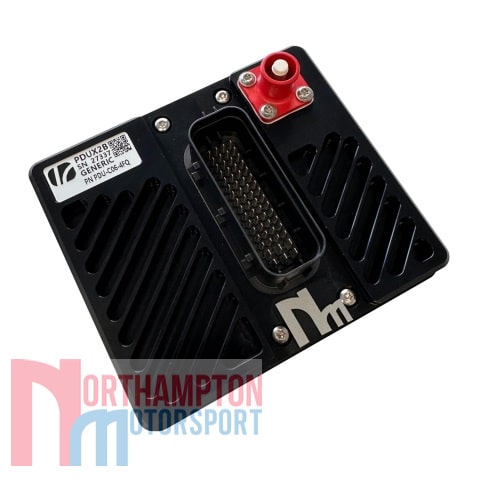
This Life Racing PDUX2 power management unit uses logical or numerical inputs from its 12 analogue inputs or from any of 3 CAN buses. The PDUX2 is calibrated using a clear graphical interface with full logic simulation ability and live monitoring.
The PDUX2 is able to operate in a low power standby state, drawing <2mA, with configurable activation based on physical or CAN input. Additionally, the PDUX2 may be paired with a Life Racing ECU to expand input and output functionality through the ‘slave-link’ feature.
Life Racing PDUX2 Power Distributor Unit Specification:
Features
- Schematic based calibration including logic simulation tool
- Numerical arithmetic including handling of analogue inputs
- Fully custom CAN across 3 buses including mux frames and retransmission (gateway), configured with the help of a graphical display and import/export tool
- Low power state woken on physical input, CAN activity, or specific CAN frame
- Optional I/O slaving to an LR ECU
Outputs
- 16 main Power Outputs
- 4 multifunction high side, low side, high side PWM (fixed 20kHz) outputs (40A continuous, soft-start inrush limiting 35A)
- 2 high side outputs (35A continuous, hard-start inrush 60A)
- 10 high side outputs (12A continuous, hard-start inrush 17.5A)
- Output linking (‘teaming’) to support very high current devices
- 2 additional low side outputs (125Hz PWM)
- All outputs short circuit and thermally protected with multi-stage in-rush control
- All outputs additionally protected by physical fuses as required by worldwide regulations
- Combined diagnostic output with reset input
- 128 scaleable CAN (‘soft’) outputs
- Custom datastream (CAN) – i.e. customisable channel current, channel state and device information
Inputs
- 12 physical switch / analogue sensor inputs including software selectable 3k ohm pull-up resistors and 4x inputs capable of programmable “wake up” functionality
- Analogue inputs may be transformed into engineering units for use in schematic
- Dedicated wake pin
- 128 CAN ‘soft’ inputs with configurable scaling, validation and debounce time
Interfaces
- 2x 100Mbit/s full duplex Ethernet (can be used as Ethernet switch)
- 3x CAN 2.0B – fully flexible
- Option for galvanically isolated CAN bus (custom projects only)
- RS232C serial interface (custom projects only)
- LIN Bus (custom projects only)
Power Supply
- 6V to 20V input voltage (12V option) or 6V to 30V input voltage (24V option)
- Dedicated logic power input
- Regulated 5V sensor supply output with full circuit protection
Sleep State
- Low power standby state with configurable wake options:
- Wake by voltage signal (1.6mA)
- Wake by any CAN activity (CAN1 only) (2mA)
- Wake by specific CAN frame (two frames required, CAN1 only) (2mA)
- Wake by CAN specific CAN frame with low latency (one frame required, CAN1 only) (10mA)
ECU Slaving
- Allows a Life Racing ECU to “claim” unused pins across a dedicated CAN bus utilising the following PDU I/O:
- Outputs 1..4 with additional functionality including H-Bridge pairing and configurable PWM frequencies
- Low Outputs 5..6 with configurable PWM frequencies
- All 12 inputs, including 4 frequency capable (optionally bipolar), and all with software selectable 3k ohm pull-up resistors
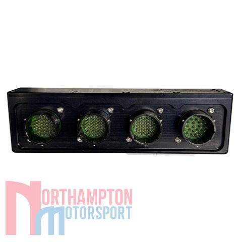
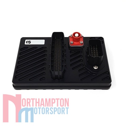
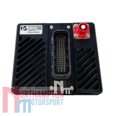
Physical
- 1 Leavyseal connector with a total of 62 pins
- Amphenol SurLok Power Stud
- Machined Aluminium enclosure
- 145x135x50mm (including connectors)
- 750 grams
- Operating Temperature -40C to +85C
Warranty and Servicing
- This equipment comes with a 1 year warranty against manufacturing defects and failures however misuse or damage will not be covered under warranty
Download Files

Download PDUX2 Data Sheet
Here at Northampton Motorsport, we also offer a full wiring and fitting service as well as engine calibration on our in house Superflow AD30 2 wheel drive chassis dyno. For more information, please contact us and a member of our team would be happy to assist with your enquiry:
Estimated dispatch time within 5 working days.
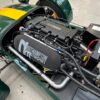
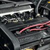
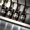
Picture for illustration purposes only. Actual parts may differ slightly in appearance.