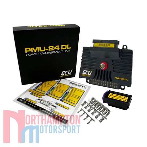
Description
One of the main advantages of the ECUMaster PMU24 is continuous current sensing and self-resetting function if the current exceeds a defined level. All output state, voltage and current information can be logged and transmitted via a CAN bus to dash displays to inform drivers of potential problems.
An additional advantage of the PMU24 system is the ability to define logic for controlling outputs. This is done with data from analogue input channels or CAN bus data, and math operations can be defined for each channel. The PMU is also equipped with LED indicators to show the status of each output.
With use of CAN bus keypads or steering wheel switches, all wiring is vastly simplified and lightened.
Two unique features are the inbuilt accelerometer and gyro for logging and “inertia switch” in case of an accident.
TECHNOLOGY:
The PMU24 is assembled according to IPC-S-815A standards to ensure product reliability. The device is manufactured on an automated assembly line with optical inspection, and automated testing (including burn-in). The PCB material and design, special surface coating and IP60 enclosure ensure reliability even in the harshest environments. Carefully selected components allow for continuous and reliable operation across a very wide temperature range (AECQ-100 GRADE 1 (-40 to +125˚C).
ECUMaster PMU24 Power Management Unit Specification:
General
- 170 Amps total continuous current
- Operating voltage: 6-22V (immunity to transients according to ISO 7637)
- Temperature range: AECQ-100 GRADE 1, -40 to +125°C
- 10x 25 Amps high-side power outputs (PWM capable)
- 6x 15 Amps high-side power outputs
- 8x 7 Amps high-side power outputs
- Up to 16 analog inputs
- 24x tricolor LED for each power output state
- 2x CAN 2.0 A/B
- 256 MB data logger memory
- Up to 500 Hz logging frequency
- Real-time clock for data stamping
- 3D accelerometer/gyroscope
- Built-in “inertia switch” in case of an accident
- Easy access to CAN-bus data (imports and exports)
- Internal data processing using logical functions, numbers, timers, and tables
- Custom PID controllers
- Fully customizable ”logic” for each output
- Flexible and intuitive client software
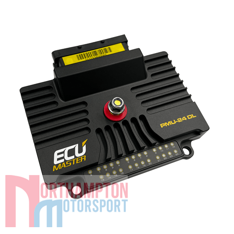
- Dimensions: 131 x 112 x 33 (mm)
- Weight 385g

Connectivity
Its important to note that to connect the ECUMaster PMU24 to a Laptop or PC, you will need the purchase the ECUMaster USB to CAN adaptor. The mating connectors and terminals are included with the PMU.
Outputs
- High current outputs 10 x 25A(cont.), 6 x 15A(cont.), 8 x 7A(cont.)* with overcurrent and overheating protection. Outputs may be paired to increase continuous current capability. Current and voltage is measured for each output
- Total current output 170A continuous
- Output current control step 100mA
- Wipers output Dedicated output with wiper braking feature
- +5V Monitored 5V, 500mA output for powering external sensors.
* 8 Analog inputs share terminals with power outputs
Inputs
- 16 Analog inputs:
- 8 x 10 bit resolution (0-5V protected), with software selectable 10K Ohm pullup and pulldowns
- 8 x 12 bit resolution (0-20V protected), with software selectable 10K Ohm pullup and pulldowns
- CAN Keypads 2 x ECUMaster keypads (4, 6, 8, 12 keys)
Other
- Output state indication 16 bicolour LEDs
- Accelerometer/Gyroscope 3D accelerometer with 3D gyroscope for logging and crash detection
- Real time clock Yes, super capacitor for backup power (up to 3 days)
- CAN BUS
- CAN interface 2 x CAN2.0 A/B
- CAN standard CAN2.0 A/B – 125, 250, 500, 1000 kbps
- Input/output stream User defined with bit masking,
- up to 100 input messages
Logging
- Logging memory 256 Mbytes
- Logging speed Variable, defined per channel, up to 500Hz
Functions
- Logical operations AND, OR, NOT, XOR, >, <, =, >=, <=, !=, isTrue, isFalse, Toggle, Flash, Pulse
- Number of functions 100
- Number of operations 250
- Update frequency 500Hz
- Special functions Wipers, Indicators
Pinout

PMU24 Pinout (v1.0)
PMU24 Pinout (mini)
Download Files

PMU Manual 1.02 (4.06.2018)
PMU software change log
Tech Notes
Configuring CAN BUS between EMU BLACK or EMU CAN and PMU16
Improved Power Control Model for PMU16
Estimated dispatch time within 3 working days.
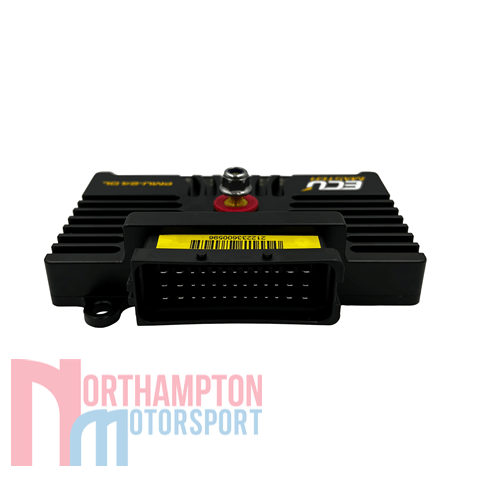
Picture for illustration purposes only. Actual parts may differ slightly in appearance.